PCB-TIPS
Accepted File Formats
Array Design
CAM Tooling Guidelines
Controlled Dielectric or Controlled Impedance?
Countersink vs Counterbore
Default Rigid PCB Specs
Dielectric Stacks
Drilling and Drill File
Fabrication Drawing/Fab Print
Fabrication Process
Final Finish Comparison
How Thick Is 1oz Copper?
How to Avoid Engineering CAM Hold
Minimizing Bow and Twist
Solder Mask
Via Tenting, Plugging, and Filling
What is Copper Thieving?
Copper Thickness
The most common unit of measure for the copper thickness on a printed circuit board is ounces (oz). But how thick is that? It's the resulting thickness when 1 oz of copper is pressed flat and spread evenly over a one square foot area. This equals 1.37 mils (1.37 thousandths of an inch). Of course not everyone thinks in mils so please refer to the chart below to convert into your preferred unit of measure.
1 oz Copper Thickness Conversion |
*To determine the thickness of 4 oz, simply multiply 1 oz thickness x 4. 1.37 mil x 4 = 5.48 mils = 4 oz |
|
1 |
oz |
|
1.37 |
mils (thousandths of an inch) |
|
0.00137 |
inch |
|
0.0347 |
mm |
|
34.79 |
µm (micron/micro meter) |
|
Most PCBs are constructed with 1 oz copper thickness. At PCB Prime, if we are not given specific specs, we will assume 1 oz when quoting and building your design. If you have determined that your design requires more current than 1 oz can carry, you'll need to consider increasing the copper weight or increasing the width of your traces. Here is a link to a current calculator: http://circuitcalculator.com/wordpress/?p=25/
Of course the thicker the copper the higher the cost, but there are certainly times where this is necessary. The cost increase is not only due to the raw material costs but processing thicker copper weights takes more time and is a little trickier to do. Keep the following chart in mind when designing your board. The more space you can allow between copper features the better. Etching the spaces (air gap) between traces is more difficult than etching a trace of the same width as your space.
General Guideline for Min Spacing by Copper Weight |
*Tighter spacing is possible but it will require an engineering review. These numbers are given as guidelines to assist you when setting your design rules. Allowing as much space as possible between copper elements will yield a more robust final product and will be cheaper to manufacture in the long term. | |
| Cu Weight | Min Recommended Space |
|
1 oz |
3.5 mil (0.089 mm) |
|
2 oz |
8 mil (0.203 mm) |
|
3 oz |
10 mil (0.254 mm) |
|
4 oz |
14 mil (0.355 mm) |
|
Glad you asked!
Bare Laminate
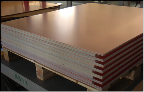 Printed circuit board material is purchased from the laminate supplier pre-clad with copper on both sides. The laminate looks like a solid sheet of copper. This pre-clad material comes in various laminate and copper thicknesses so PCBs can be constructed with different thicknesses and finished copper weights.
If your target finished copper thickness is 1 oz, we'll start with a ½ oz sheet of material. This is ½ oz on each side.
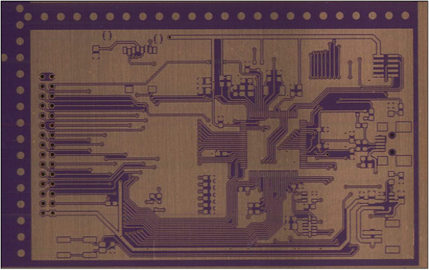
Imaging
Because the production panels are completely covered with copper, the excess copper needs to be removed to reveal your design. To do this, a 1:1 size image of your design is photo plotted onto a film. The copper clad panel is coated with an etch-resistant material and your image is then transferred onto the etch resist.
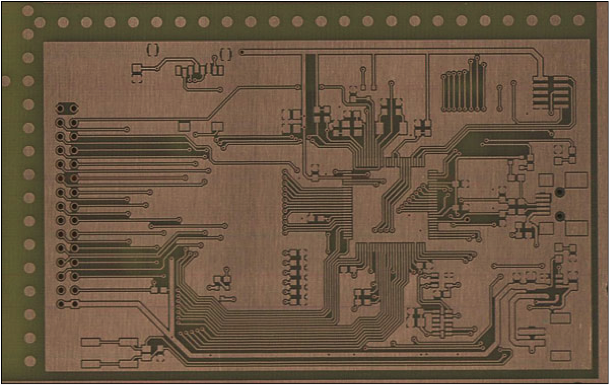
Etching
Next, the panel is submerged in a chemical bath where only the protected areas of the panel will have copper remaining. This is where the spacing between your copper features are critical.
Etching is a subtractive process, meaning excess material is removed; therefore, there is no way to prevent the chemical solution from removing the sides of the traces as it etches down toward the bare laminate.
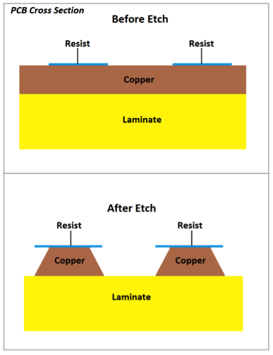 As soon as the chemicals begin etching down toward the laminate, they also begin etching laterally underneath the resist. Since the copper closest to the resist will be exposed longest, these areas will have the most lateral etching resulting in a trapezoidal shape to copper features. As you can imagine, the thicker the copper, the more time it will take for the solution to etch all the way down to the bare laminate to define your pattern.
One of the many things that is done during the tooling and setup of your order is the size of your copper features are slightly increased to compensate for lateral etching. This compensation will reduce the spacing between features. This, combined with the longer required time spent in the etchant, is why more space is needed between elements on thicker copper boards. If elements are too close together, it won't be possible to etch down to the laminate before the copper features are reduced too significantly or are etched completely away.